English
 русский
 Español
 Deutsch

Content
The technician pulls a worn automatic slack adjuster off a trailer axle, measures the spline opening, counts the teeth on the camshaft gear, and reaches for the new part. The drawing on the box shows the arm profile, the splined hub and the mounting hole pattern, but every line needs to be read correctly if the replacement is going to fit the first time. An automatic slack adjuster diagram is the bridge between an axle in the workshop and a part in the catalogue. This article explains how to read those diagrams, what each measurement controls, and how the drawing helps you order the right replacement without guesswork.
What an Automatic Slack Adjuster Diagram Shows
An automatic slack adjuster diagram is a technical drawing of the lever arm that connects the brake chamber push rod to the S-cam shaft. It is usually presented from two angles. The side profile shows the arm shape, the arm length, and the clevis pin hole. The end view shows the splined hub opening or, for trailer-type adjusters, the mounting flange and gear teeth.
The side profile communicates:
- Arm length: the centre-to-centre distance between the splined hub and the clevis pin hole. This dimension sets the lever ratio of the brake.
- Clevis connection: the hole where the push rod clevis pin passes through, connecting the adjuster to the brake chamber push rod.
- Left or right orientation: the arm is cast to curve toward or away from the axle, so the drawing marks which side of the vehicle the adjuster is designed for.
The end view communicates:
- Spline count and diameter: for example, 10 spline and 1.5 inch diameter, the standard interface for many American-type heavy-duty axles.
- Teeth count: for trailer-type adjusters, the number of gear teeth that engage the camshaft, for example 10, 25 or 28 teeth.
- Mounting hole pattern: for trailer-type adjusters, the number and position of bolt holes, typically a 3-hole pattern.
In addition to the external views, many diagrams include a cutaway of the internal mechanism showing the worm gear, worm wheel, adjusting pawl and one-way clutch. That cutaway is useful because it explains how the adjuster automatically takes up the clearance between the brake lining and the drum without manual intervention.
Using the Diagram as a Diagnostic Tool
The diagram is not only a fitment reference. It is also a diagnostic aid. The arm length dimension, for example, directly affects brake chamber stroke. A longer arm gives the brake chamber a mechanical disadvantage, requiring more push-rod travel to rotate the S-cam the same angle. A shorter arm does the opposite. If an incorrect adjuster is installed, the chamber stroke will fall outside the recommended range, leading to a brake that is slow to apply or slow to release. Understanding how automatic slack adjusters contribute to overall brake system safety starts with reading these dimensions correctly.
When you see a vehicle come in with an out-of-adjustment brake, tracing the problem back to the adjuster is easier if you can visualise what the diagram shows: the push rod pushes the arm, the arm rotates the S-cam through the splined hub, and the cam spreads the brake shoes. Any wear, seizure or incorrect fit along that chain shows up as an abnormal stroke reading.
Key Dimensions That Decide Fitment
The table below lists the dimensions that typically appear on an automatic slack adjuster diagram and what each one controls in practice.
| Dimension | What it controls | Typical values |
|---|---|---|
| Spline count | Engagement with the S-cam shaft | 10 spline |
| Spline diameter | Hub fit on the camshaft end | 1.5 inch |
| Arm length | Lever ratio and brake chamber stroke | 5, 5.5, 6, 6.5 inches |
| Teeth count | Trailer camshaft engagement | 10, 25, 28 teeth |
| Mounting holes | Trailer flange attachment | 3 holes |
| Left / right orientation | Correct arm position on the axle | Left side, right side |
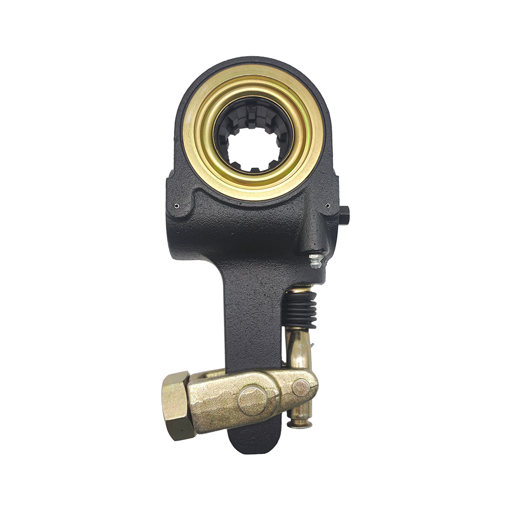
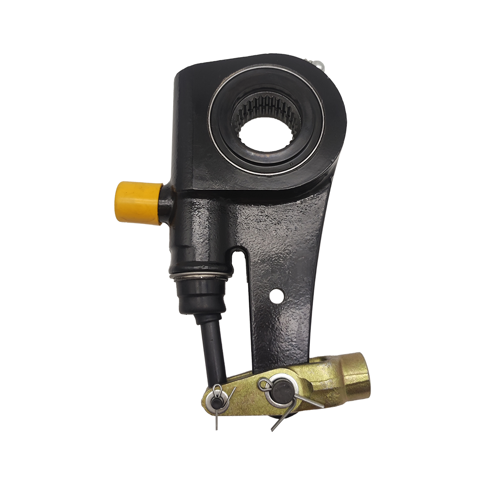
For American-type applications, the spline and diameter pair is the primary interface. A common specification is 10 spline by 1.5 inch diameter. When a diagram shows this pair, it is a strong indication that the adjuster is designed for the standard heavy-duty tractor and trailer S-cam shaft. An AS1132 American-type automatic slack adjuster is built to this specification, which makes it straightforward to match against the original part.
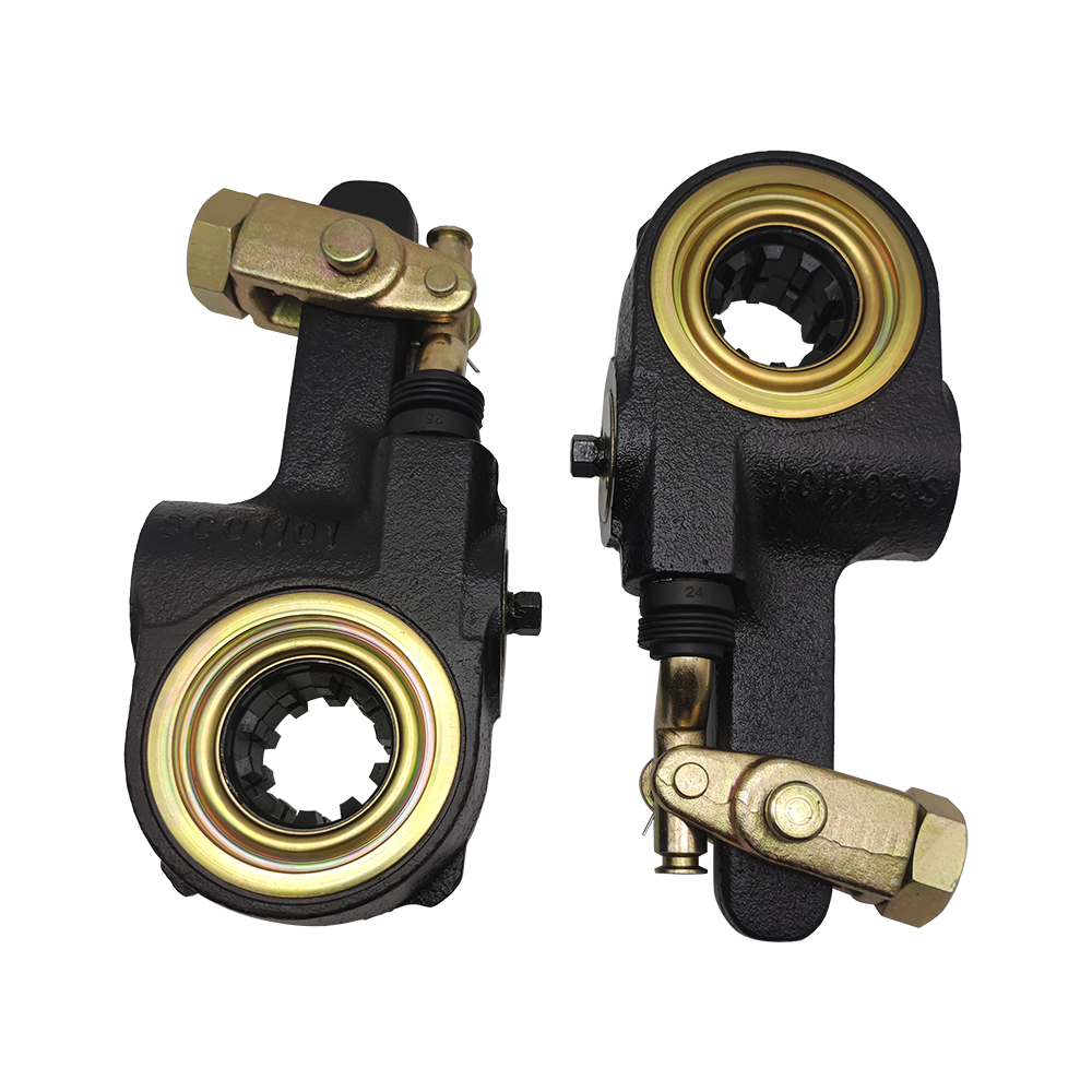 OEM AS1132 5.5" AS series american type 10-spline, 1.5" dia automatic slack adjuShaoxing Tiean Auto Fittings Manufacturing Co., Ltd is China OEM AS1132 5.5' AS series american type 10-spline, 1.5' dia automatic slack ...View Product →
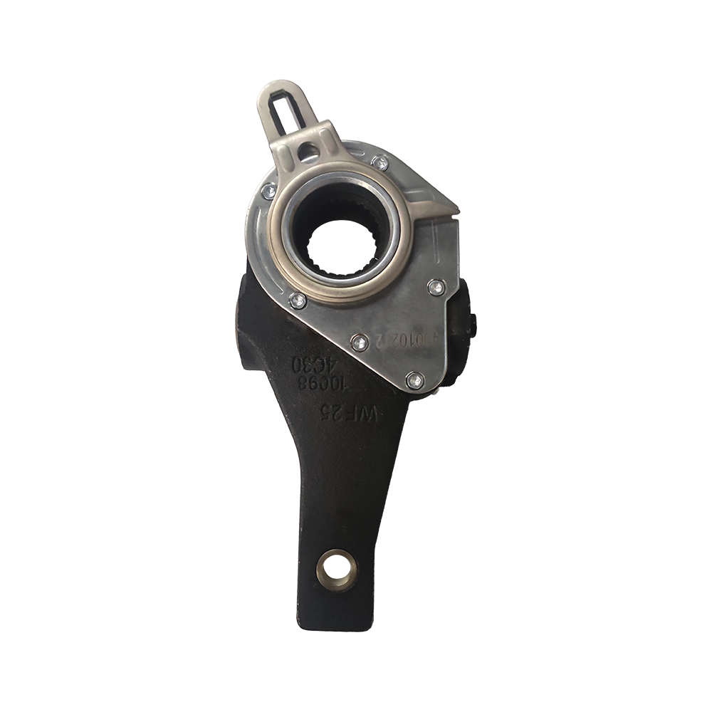
Trailer-type adjusters use a different interface. Instead of a splined hub, many trailer slack adjusters mount through a flange with bolts, and the gear on the flange engages with the camshaft. The diagram for these adjusters shows the number of teeth and the number of bolt holes, for example "25 teeth, 3 holes." A 25-teeth 3-hole AA1 trailer automatic slack adjuster matches this pattern and is a direct replacement for the corresponding original unit.
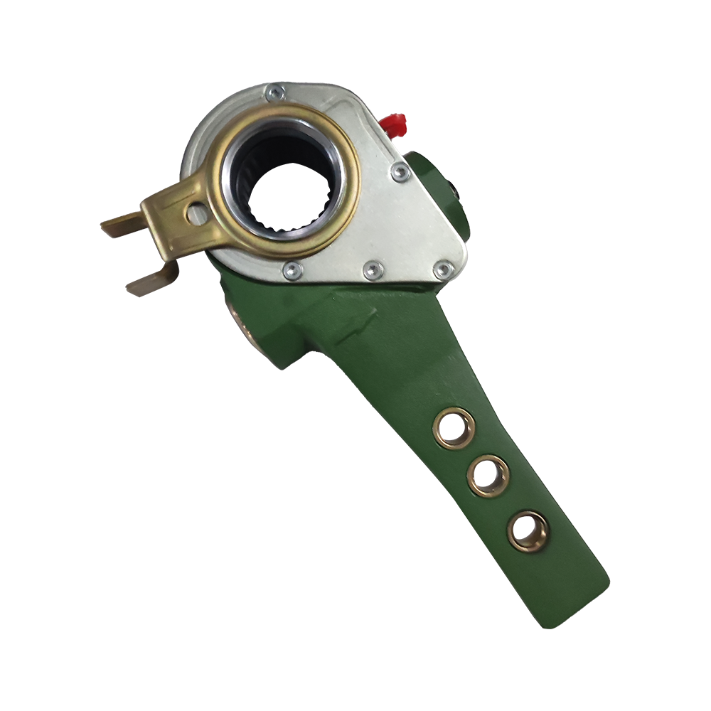 OEM 79863 AA1 trailer automatic slack adjuster 25 teeth 3 holes heavy duty truckShaoxing Tiean Auto Fittings Manufacturing Co., Ltd is China OEM 79863 AA1 trailer automatic slack adjuster 25 teeth 3 holes heavy duty t...View Product →
How the Internal Mechanism Relates to the Diagram
The cutaway portion of an automatic slack adjuster diagram deserves attention because it explains the operating logic. When the driver applies the brakes, the push rod extends and rotates the adjuster arm. The worm wheel, attached to the S-cam shaft, turns with the arm. If the push-rod travel exceeds a pre-set threshold, the adjusting pawl advances the worm gear by one tooth, which rotates the worm wheel slightly and takes up clearance. When the brake is released, the one-way clutch prevents the worm gear from reversing, so the adjustment is retained.
This is why automatic slack adjusters are designed to maintain the lining-to-drum clearance and the brake chamber stroke within specification. If the internal mechanism wears, seizes or is assembled incorrectly, the adjuster stops compensating for lining wear. The result is a stroke that grows over time, and eventually a brake that requires the driver to push the pedal harder to get the same stopping force. Knowing the common signs of a malfunctioning automatic slack adjuster, such as an increasing stroke reading or a clicking noise during brake application, allows a technician to catch the problem before it becomes a safety issue.
Using the Diagram When Ordering a Replacement
When ordering a replacement, the diagram of the new part should be compared side by side with the original part before purchase. Three rules cover most situations.
- Identify the spline and diameter first. Count the splines on the original camshaft and measure the hub opening. Compare this with the end view of the replacement diagram. For American-type axles, 10 spline by 1.5 inch is the dominant standard; European and Asian applications may use different numbers.
- Confirm the arm length. Measure from the centre of the splined hub to the centre of the clevis pin hole on the original part. The replacement diagram should show the same centre-to-centre dimension. A one-inch difference in arm length is enough to change the brake chamber stroke noticeably.
- Check the left or right orientation. If the original part has an "L" or "R" marking, or if the vehicle application identifies the side, select the matching replacement. The diagram will normally indicate the side in the part name or in the drawing itself.
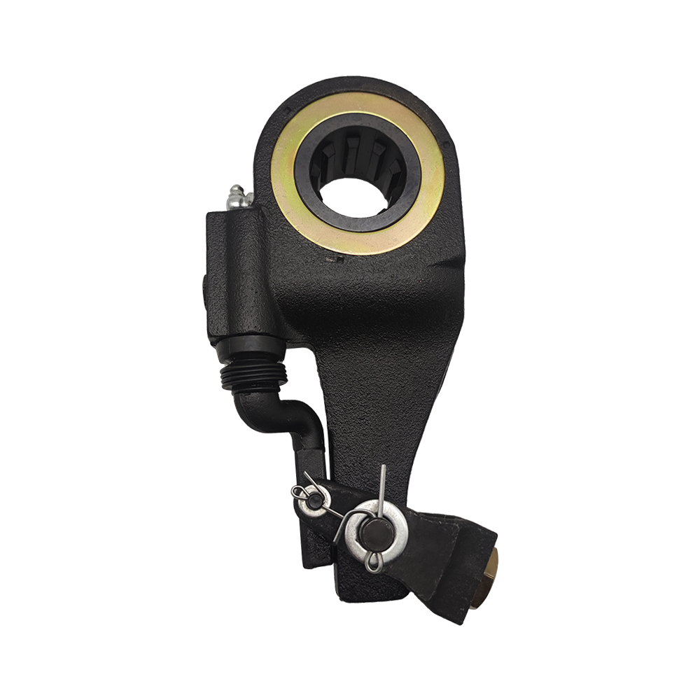
For vehicles outside the American standard, the OEM part number or an interchange reference is the quickest way to confirm fitment. For example, a Daewoo bus automatic slack adjuster application may rely on an OEM reference such as 79251 for the right side. Matching the diagram of the replacement against the removed part, including the arm curve and the clevis hole position, is the final check before installation.
Common Mistakes When Reading Diagrams
Three mistakes come up repeatedly in workshop practice.
- Confusing the arm length with the overall length of the casting. The arm length in a diagram is measured centre-to-centre between the splined hub and the clevis pin hole, not from one outer edge to the other. Using the overall length as a reference can lead to selecting an adjuster with the wrong lever ratio.
- Misreading the drawing orientation. Some diagrams show the adjuster from the rear of the axle, some from the front. If you hold the drawing in the same direction as the installed part, left and right side markings can be reversed. Always confirm the side designation in the part description rather than relying on the angle of the drawing.
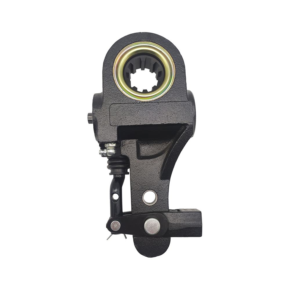
- Assuming that all trailer adjusters with the same bolt pattern are interchangeable. A 3-hole flange may look identical, but the tooth count on the gear must match the camshaft. A 3-hole S-ABA trailer automatic slack adjuster
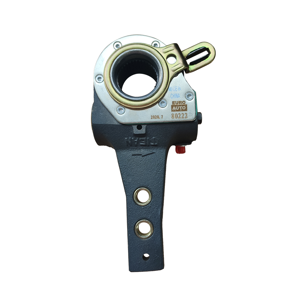 OEM 80222 3 Hole S-ABA trailer automatic slack adjuster Manufacturers, FactoryShaoxing Tiean Auto Fittings Manufacturing Co., Ltd is China OEM 80222 3 Hole S-ABA trailer automatic slack adjuster manufacturers and fa...View Product → for a 10-tooth camshaft will not fit a 25-tooth camshaft, even though the mounting holes line up. Counting the teeth on the original part before ordering avoids that mismatch.
An automatic slack adjuster diagram is worth more than the paper it is printed on. It tells you whether the part will fit, why it works, and where to look when a brake performs poorly. For technicians, reading the diagram accurately prevents the most common ordering errors. For fleet buyers, it is the difference between a part that goes on the truck and a part that goes back in the box. Comparing the diagram with the original part takes less than a minute, and it is the most reliable habit to build into any brake repair or parts purchase.